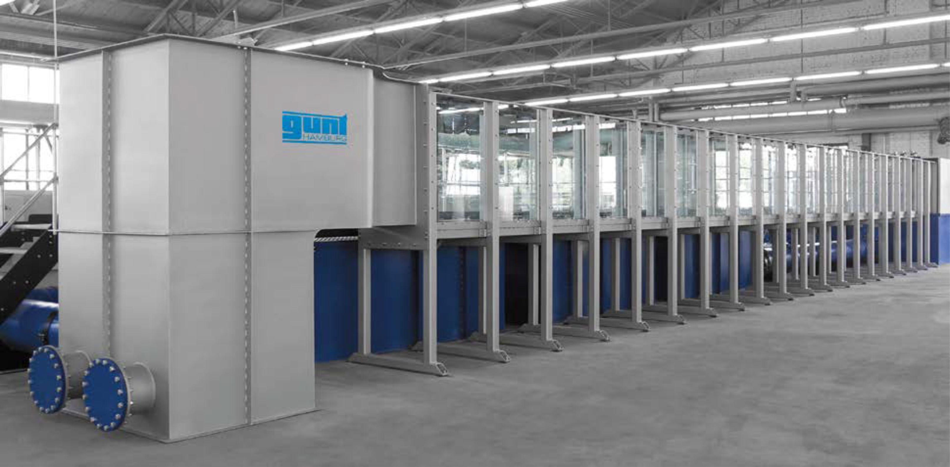
GUNT experimental flumes
GUNT experimental flumes
Open-channel flow at the laboratory scale
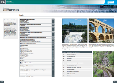
Hydraulic engineering is a crucial part of engineering. How do we achieve the necessary river depth for ships? How does open-channel flow change during flooding? In order to understand answers to these questions and develop possible solutions, experimental flumes are used in teaching and research.
Content
- Overview of GUNT experimental flumes
- Accessories for GUNT experimental flumes
- Automated operation and data acquisition
- Download
 |
GUNT offers extensive multimedia educational material on the fundamentals open-channel flow as a » E‑learning course. |
Overview of GUNT experimental flumes
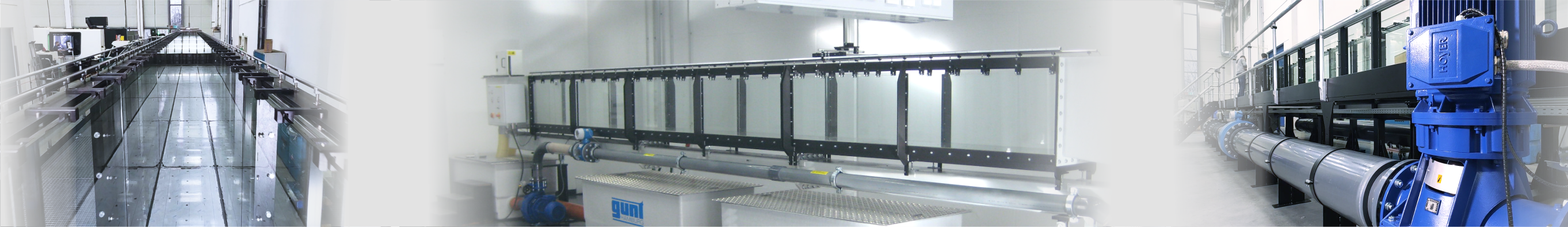
GUNT experimental flumes and their accessories open up a wide range of experiments and demonstrations on the topics of open-channel flow, running waters, hydraulic engineering and coastal protection. They form the expandable foundation for custom investigations and research work.
Design features
- rigidity against deformation
- side walls made of tempered glass
- all surfaces in contact with water are made of corrosion-resistant materials
- low-turbulence flow at the entrance to the experimental section
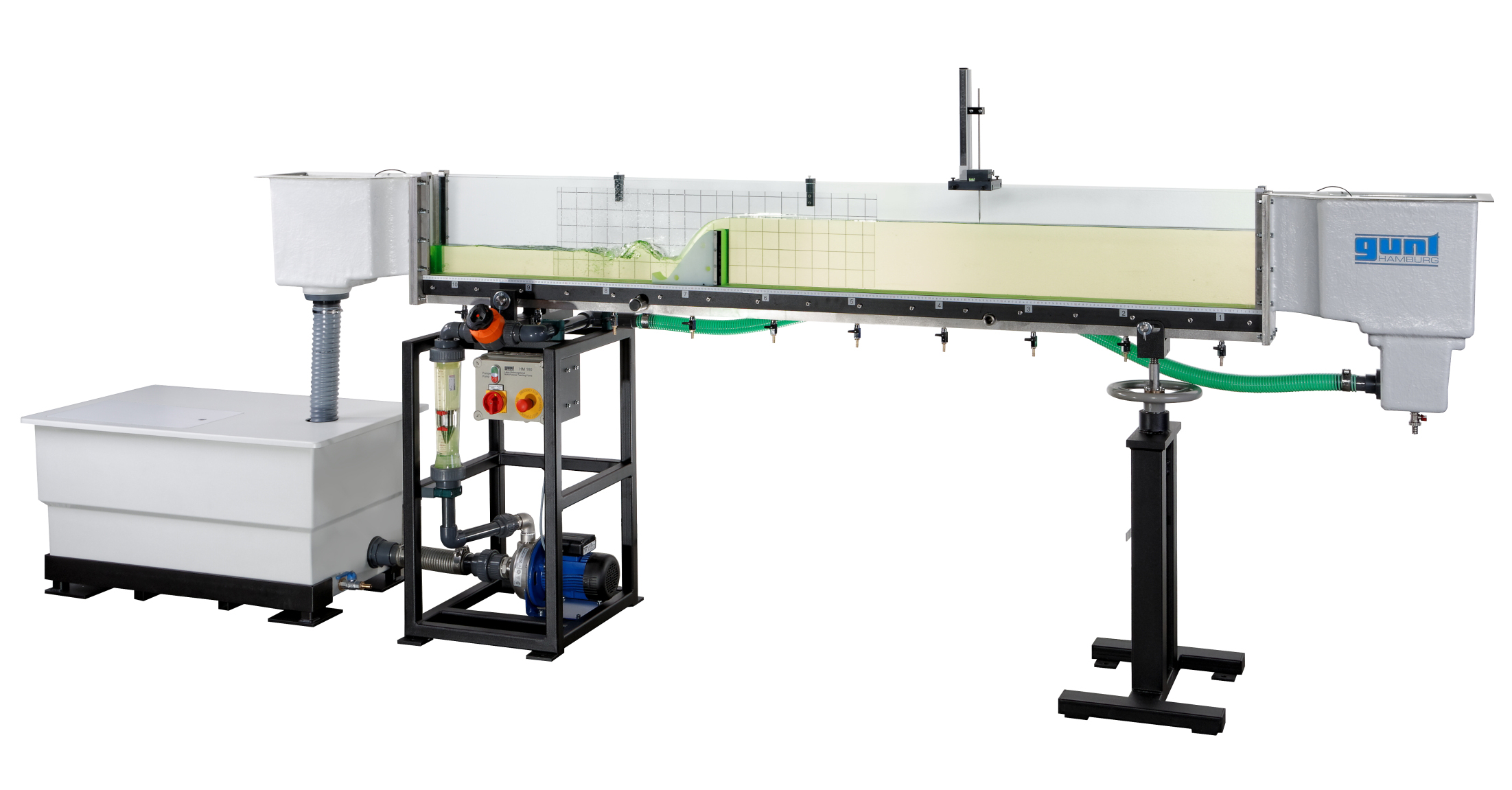
The HM 160 flume is perfectly suited as an introduction to the topic of open-channel flow and the demonstration of many of the basic principles. This flume is compact and requires little space.
HM 160
Experimental flume 86x300mm
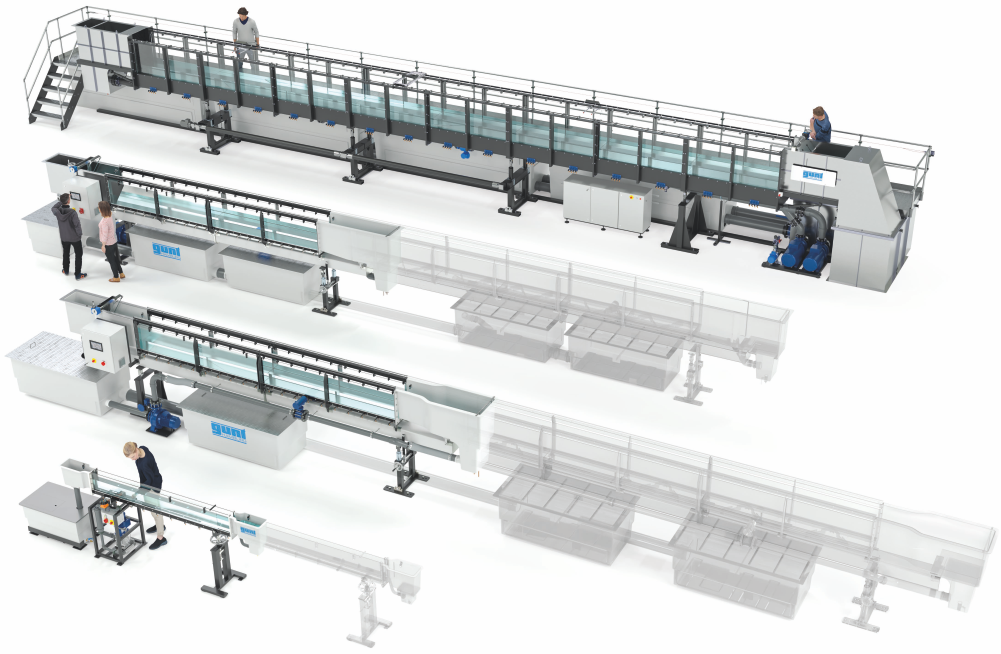
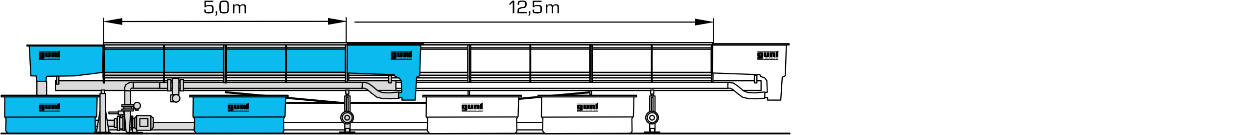
The HM 162 experimental flumes can be supplied in four different lengths. The “short” experimental flume, with an experimental section of 5m, can easily be set up even in smaller laboratories. As the length of the experimental section increases, the observation section upstream and downstream of obstacles increases.
HM 162
Experimental flume 309x450mm

The HM 163 experimental flumes can be supplied in four different lengths. The “short” experimental flume, with an experimental section of 5m, can easily be set up even in smaller laboratories. As the length of the experimental section increases, the observation section upstream and downstream of obstacles increases.
HM 163
Experimental flume 409x500mm
The experimental flume HM 161 is the largest within the GUNT product range. The flow velocities that can be achieved in the experimental flume, and the long length of the experimental section, are the perfect conditions for designing your own projects. These projects can be very close approximations of reality.
HM 161
Experimental flume 600x800mm
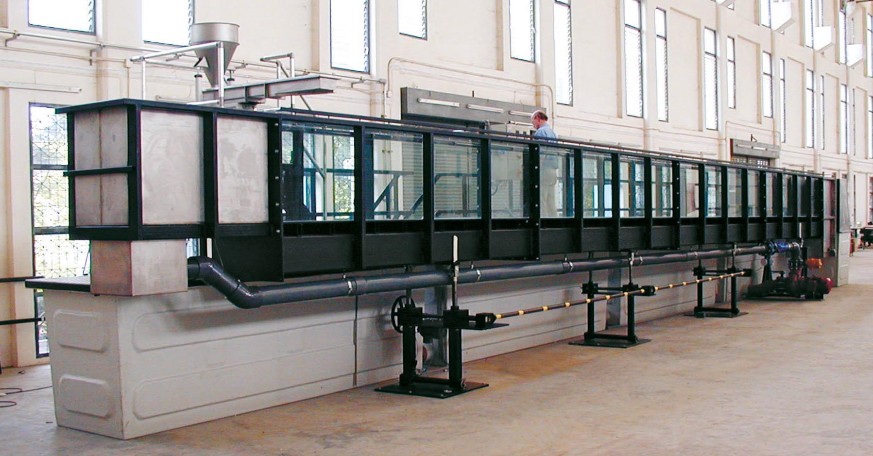
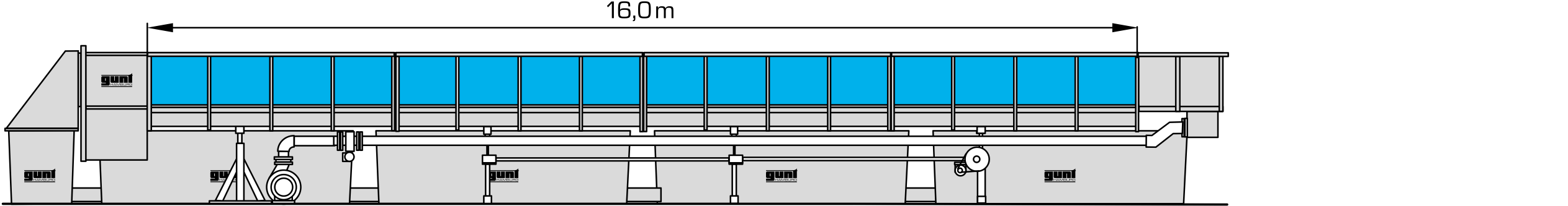
In addition to our range of standard products, we at GUNT offer innovative experimental flumes that suit the customer's needs and space requirements.
Customised solutions

In this video, you can see a customised flume made by GUNT. The experimental section has a length of 16m and a flow cross-section of 600x1200mm. It is equipped with a wave generator and an inline pump with reversible flow direction.
Accessories for GUNT experimental flumes
For each of the experimental flumes, there is a variety of models for discharge control, such as weirs, sills, stilling basins, as well as wave generators, beach elements and bridge piers. Technical solutions for sediment feed and removal are also available. In addition, we can also provide specially adapted instrumentation such as water level gauges, pitotstatic tubes, tube manometers and velocity meters.
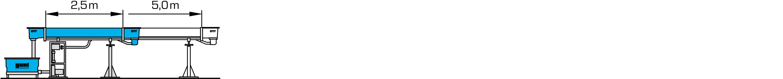
A sluice gate is a vertical wall causing backwater in the flume. The core element of a radial gate is a wall with the shape of a segment of a circle. The gate causes backwater in the flume. HM 16x.30 contains four different plate weirs as sharp-crested weirs: typical measuring weirs with defined openings (Thomson weir, Rehbock weir, Cipoletti weir) and a rectangular weir with optional aeration. » HM 160.30 Set of plate weirs, four types » HM 161.30 Set of plate weirs, four types HM 16x.31 contains a cuboid shaped weir body with a sharp edges. Two additional elements can be fixed at the weir body to create rounded edges. Free and submerged overfall can be clearly demonstrated. » HM 160.31 Broad-crested weir » HM 161.31 Broad-crested weir Sills are used to reduce the flume slope to decrease erosion processes at the flume bottom. HM 16x.33 is a weir according to E. S. Crump with defined inclinations both upstream and downstream. The Crump weir is preferably used as a sill. A flow transition to supercritical discharge occurs during flowing over the weir body. At the end of the weir downstream side, the supercritical discharge has a high flow energy. The excess part of this energy can cause damages. Therefore, energy should be dissipated. The elements for energy dissipation are used together with the ogee-crested weir HM 160.32. With the aid of stilling basins and elements like chute blocks, baffle blocks, and end sills, the flow energy is dissipated. » HM 160.35 Energy dissipation elements » HM 161.35 Energy dissipation elements The weir itself consists of a massive damming body. The pressure measurement is realised via bores perpendicular to the surface of the downstream side of the weir. » HM 160.34 Ogee-crested weir with pressure measurement » HM 161.34 Ogee-crested weir with pressure measurement Siphon weirs are used as spillways in dams. They have a high specific discharge capacity. The rake HM 16x.38 enables to vary the rake flow resistance using different bar profiles and different angles of inclination. Three bar sets with different profiles are included. HM 16x.30 contains four different plate weirs as sharp-crested weirs: typical measuring weirs with defined openings (Thomson weir, Rehbock weir, Cipoletti weir) and a rectangular weir with optional aeration. » HM 160.30 Set of plate weirs, four types » HM 161.30 Set of plate weirs, four types Venturi flumes are specially shaped flumes with defined lateral contraction. Parshall flumes are venturi flumes with a profiled bottom. The ratios of constriction and enlargement are defined. The trapezoidal flume HM 16x.63 has a trapezoidal flow cross-section. In contrast to Parshall flumes, they often have a smaller pressure head loss for the same discharge and are more suitable for small discharges. Sills are used to reduce the flume slope to decrease erosion processes at the flume bottom. For the same discharge, the flow behaviour of a river depends mainly on the flume slope and on the flume roughness. The flume roughness is changed using the flume bottom HM 16x.77. » HM 160.77 Flume bottom with pebble stones » HM 161.77 Flume bottom with pebble stones HM 16x.33 is a weir according to E. S. Crump with defined inclinations both upstream and downstream. The Crump weir is preferably used as a sill. HM 16x.46 contains several piers with different profiles typical for bridge piers. A clamping device fixes the pier in the experimental flume. » HM 160.46 Set of piers, seven profiles » HM 161.46 Set of piers, seven profiles Culverts are crossing structures in running waters and allow the passage of water. They may be pipes that are laid under a road, allowing the flume to cross. The wave generator HM 16x.41 is available as an accessory for all experimental flumes and generates periodic, harmonic waves with different wavelengths and/or wave heights. An electric motor drives a crank disk, which is connected to a plate via a driving rod. The plate performs a harmonious stroke movement. The speed of the crank disk, in other words the frequency, with which the plate is moved back and forth can be adjusted, therefore affecting the wavelength of the generated waves. Furthermore, the stroke is finely adjustable, so that the wave height (amplitude) can be varied. In combination with the wave generator HM 16x.41, HM 16x.80 is used to study the wave run-up at different beaches. The inclination of the beach can be changed in 5% steps in order to observe the wave run-up under different conditions. » HM 160.80 Set of beaches: plain, rough, permeable » HM 161.80 Set of beaches: plain, rough, permeable HM 16x.72 enables experiments on bed-load transport and consists of a sediment trap and a bucket for sediment feed. The sediment trap prevents the sediment of entering into the pump or the flow meter of the experimental flume. The sediment feeder essentially consists of a vibrating conveyor, via which sediment is introduced into the experimental section. The feeder is usually mounted above the inlet to the experimental section. HM 162.71 considers the bed-load transport and consists of a sediment trap, a sediment feed and a pipe system with a pump for delivering the mixture of water and sediment from the trap back to the sediment feed between two experiments. » HM 161.71 Closed sediment circuit The discharge depth can be measured using a level gauge. There are two different types available: analogue or with digital display. For the larger experimental flumes HM 162, HM 163 and HM 161, the level gauge is mounted on the moveable instrument carrier HM 16x.59. The pitotstatic tube HM 162.50 is used to measure the flow velocity in the experimental flume. For the larger experimental flumes HM 162, HM 163 and HM 161, the pitotstatic tube is mounted on the moveable instrument carrier HM 16x.59. The core element of the velocity meter is an impeller that is rotated by the flow. The speed of the impeller is proportional to the flow velocity. For the larger experimental flumes HM 162, HM 163 and HM 161, the velocity meter is mounted on the moveable instrument carrier HM 16x.59. A PIV system (Particle Image Velocimetry) is used to record velocity fields in the experimental flume. Depending on the positioning of the light source, the instrument carrier HM 16x.82 or the HM 162.83 glass cut-out is required for the base of the flume. A subsequent installation of the glass cut-out is not possible. The accessory HM 16x.59 is intended as carrier for instruments, e.g. the pitotstatic tube HM 16x.50 or the level gauge HM 16x.52. Using the carrier, the used instrument can be moved to nearly every point of the flow. » HM 161.59 Instrument carrier Up to 10 or 20 measuring points along the experimental section of HM 162 are connected to the tube manometers using hoses. The manometers are fitted with scales directly indicating the discharge depth of the corresponding measuring point. » HM 160.53 Ten tube manometers » HM 161.53 20 tube manometers Using HM 16x.13, the discharge depths in form of pressure heads are recorded. For this purpose, the measuring amplifier is connected to the switch cabinet of the experimental flume and automatically identified by the PLC. » HM 161.13 Electronic pressure measurement, 10x 0...100mbar » HM 162.13 Electronic pressure measurement, 10x0...50mbar (also suitable for HM 163) The vibrations are caused by the interaction between the water and the pile. For example, flow around a pile can lead to the formation of a Karman vortex street. The experimental flumes can be inclined. The inclination adustment of HM 162/HM 163 can be changed to a spindle-type lifting gear with electric drive motor. HM 161 includes an electrical inclination adjustment as standard. » HM 162.57 Electrical inclination adjustment (also suitable for HM 163) HM 16x.14 is laid out for the experimental flume with an experimental section of 5m length. The gallery can be extended stepwise by 2,5m by adding extension elements HM 16x.15. The gallery for the experimental flume makes it easy to put accessories into the experimental section or take them out. The experimental section of the flume can be extended by adding extension elements. The extension elements are mounted during the setup of the experimental flume. It is not possible to install them at a later date. » HM 160.10 Extension element of the experimental flume The water tank HM 16x.20 is necessary if the the flume is extended to a larger experimental length to ensure that there is always sufficient water available. The HM 160 experimental flume can be equipped with the UV system for disinfecting water. The treatment capacity of the UV system is matched to the experimental flume.
Control structures
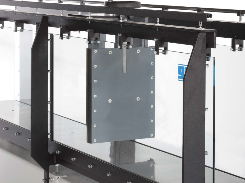
Sluice gate
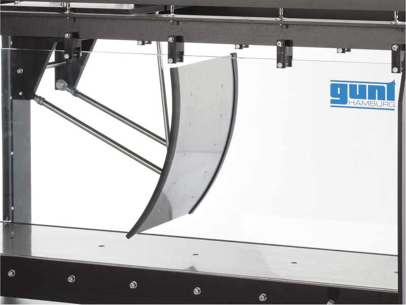
Radial gate
Sharp-crested weirs/ plate weirs
Broad-crested weir
Sill
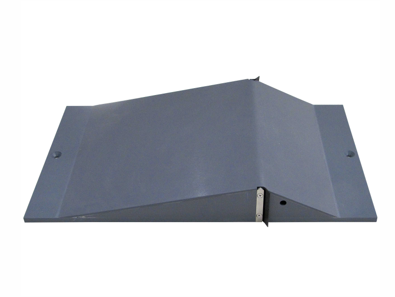
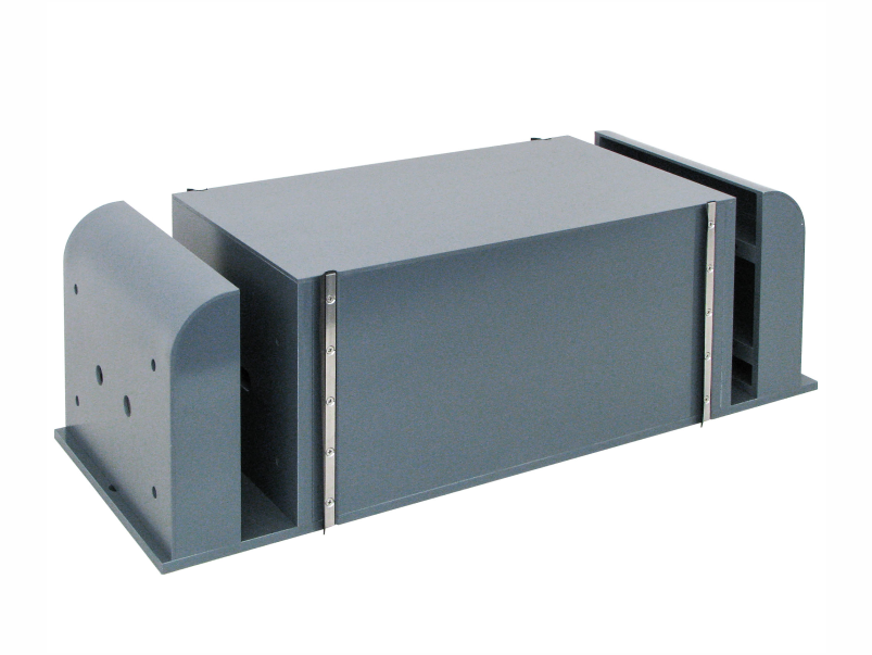
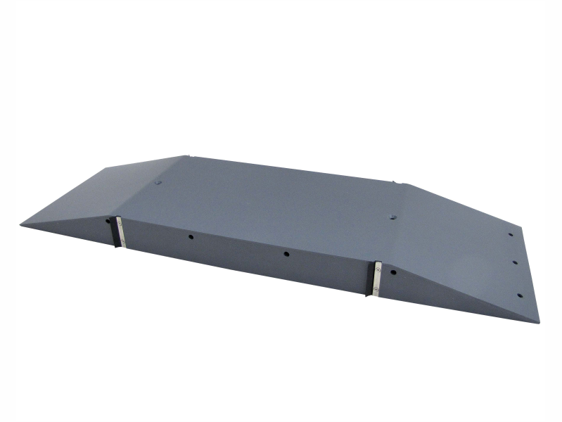
Crump weir
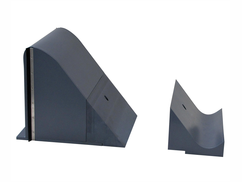
Ogee-crested weir
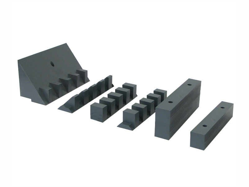
Energy dissipation elements
Ogee-crested weir with pressure measuring points along the weir downstream side
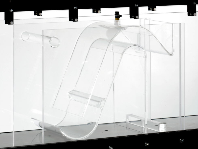
Siphon weir
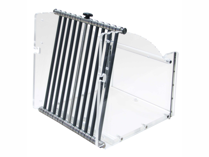
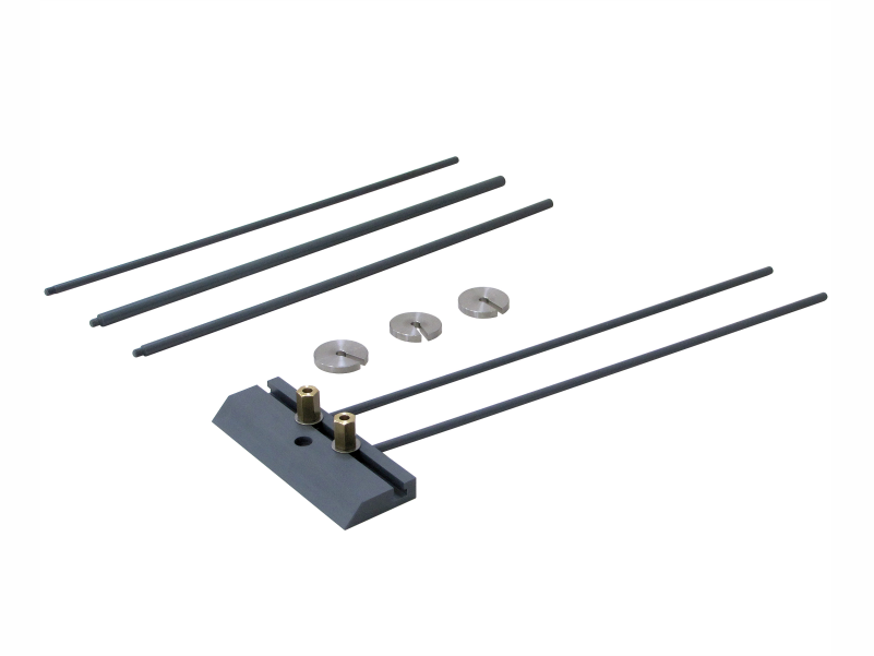
Rake
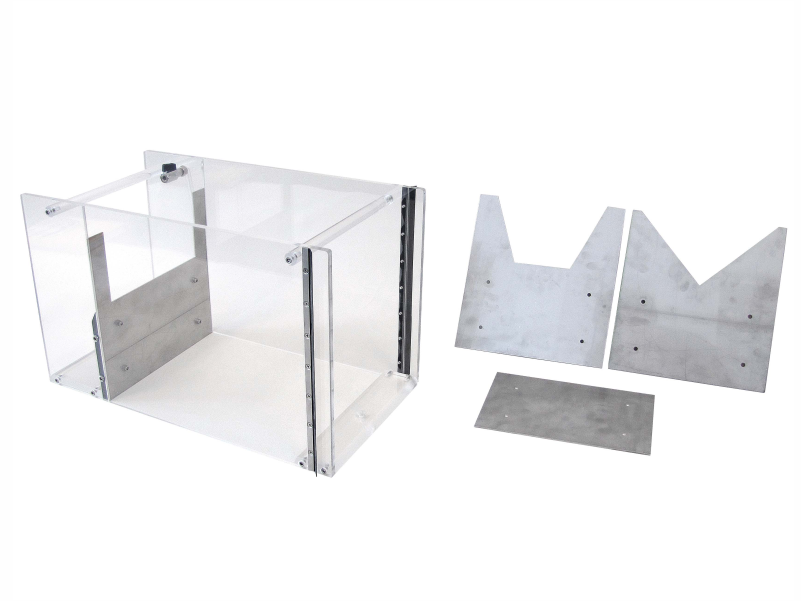
Discharge measurement
Sharp-crested weirs/ plate weirs
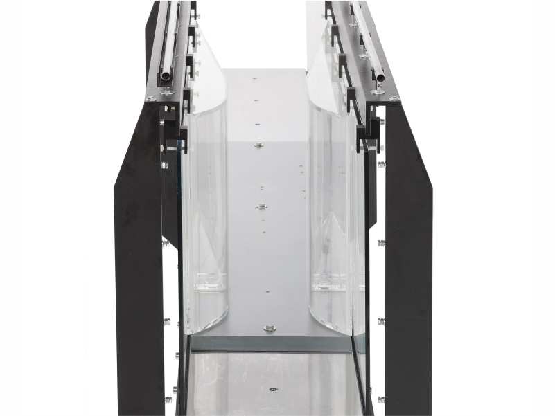
Venturi flume
Parshall flume
Trapezoidal flume
Change in cross-section
Sill
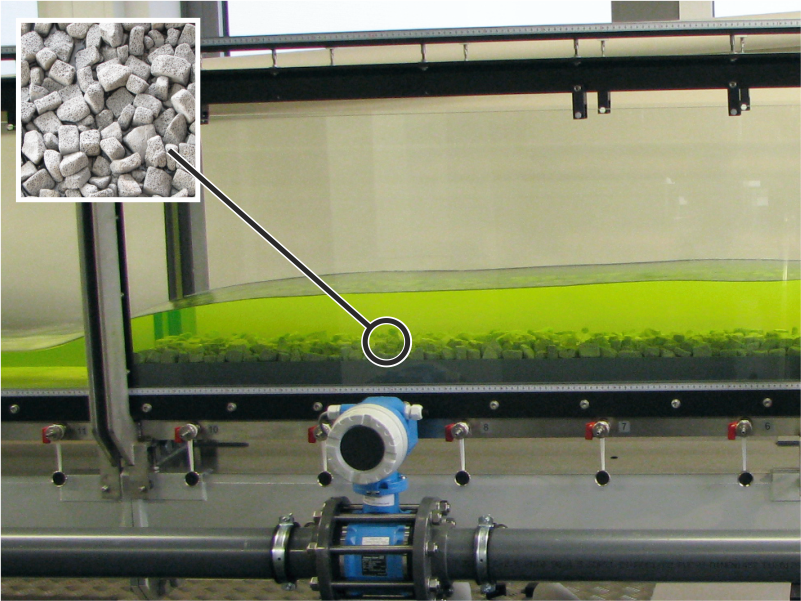
Flume bottom with pebble stones
Crump weir
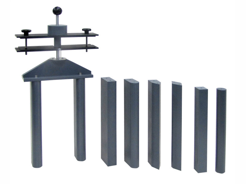
Piers
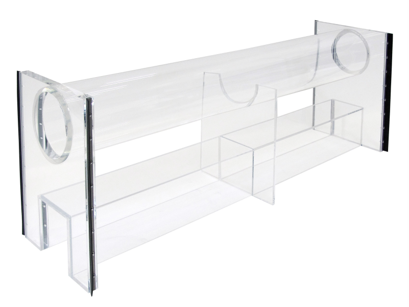
Culvert
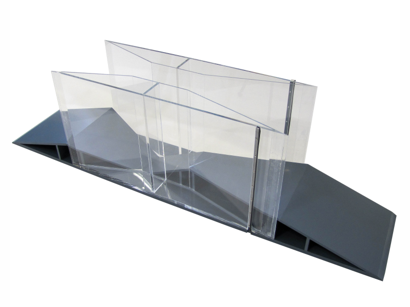
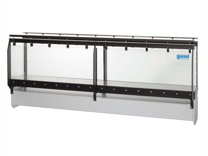
Wave generator and beaches
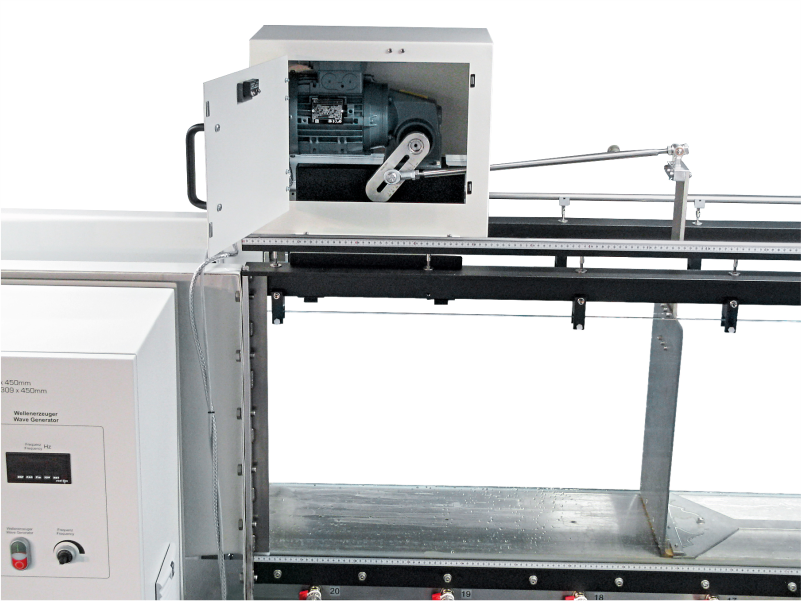
Wave generator
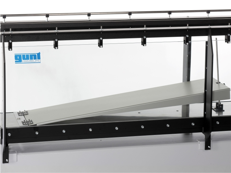
Beaches
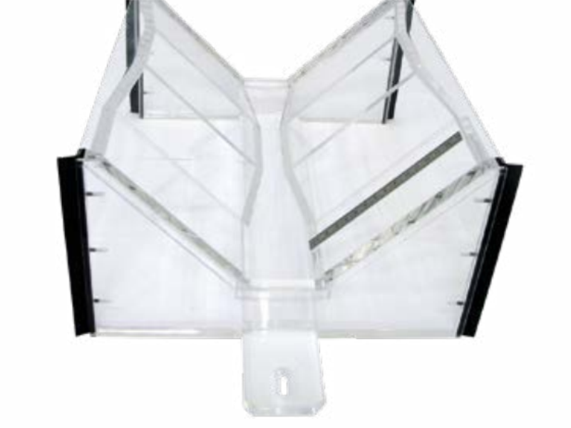
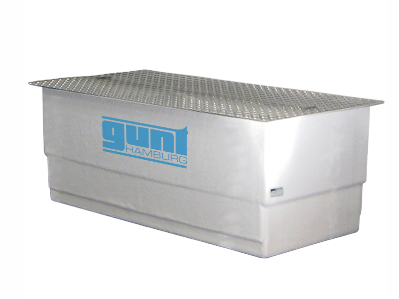
Sediment transport / sediment feed / sediment trap
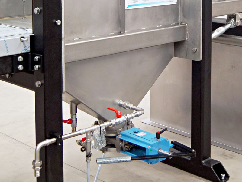
Sediment trap
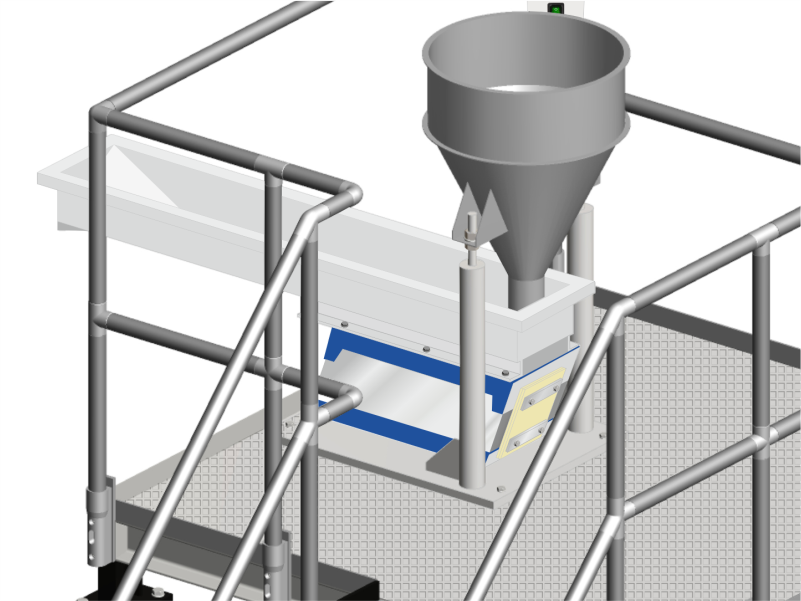
Sediment feeder
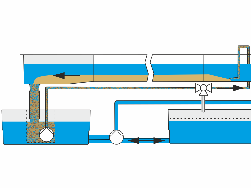
Closed sediment circuit
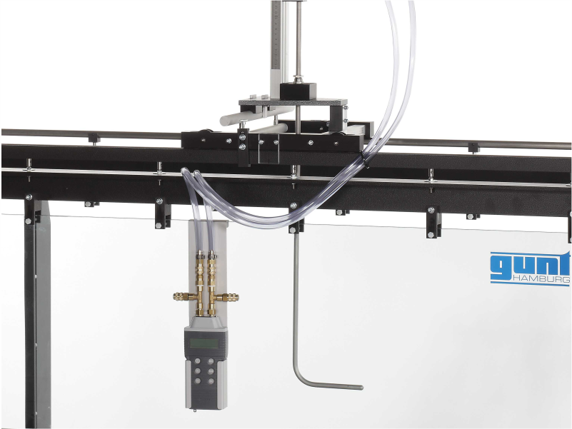
Measuring instruments
Level gauge
Velocity measurement via pitotstatic tube
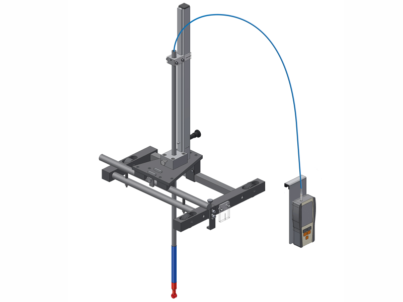
Velocity measurement via velocity mete
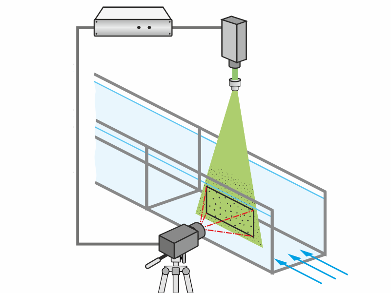
PIV-System
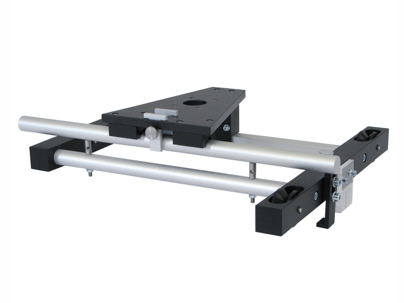
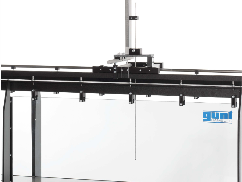
Instrument carrier

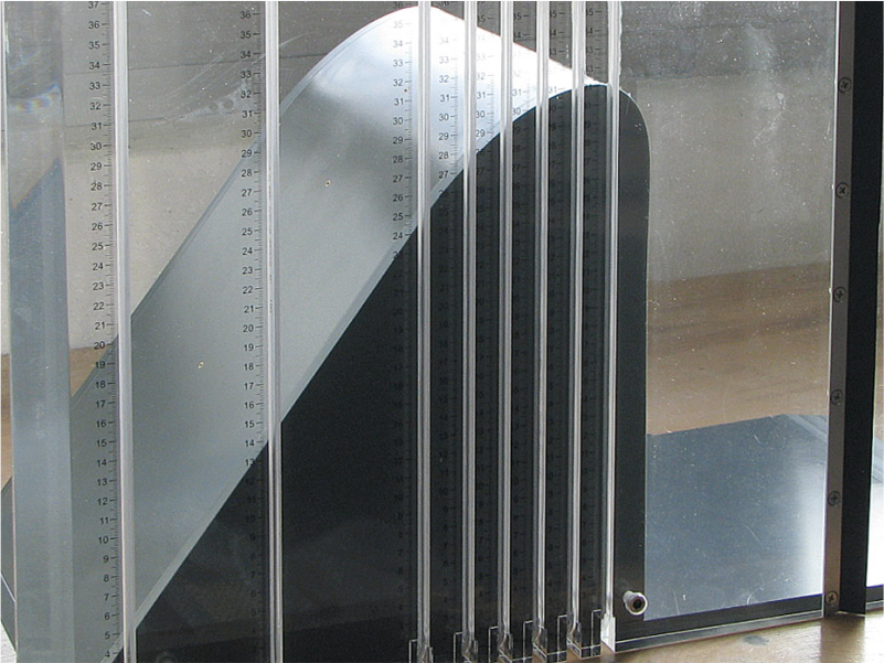
Pressure measurement
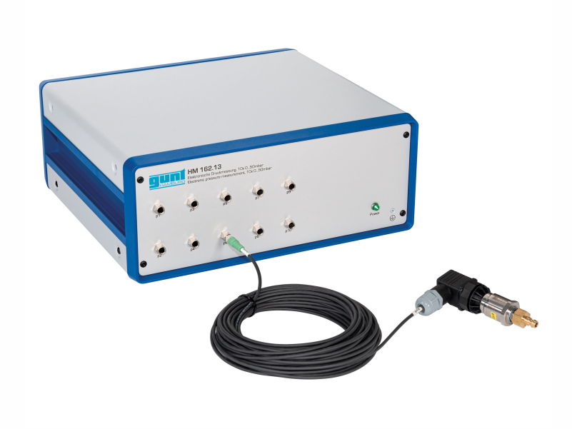
Electronic pressure measurement
Other accessories
Flow-induced vibrations
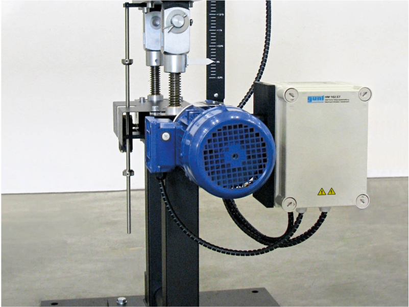
Electrical inclination adjustment
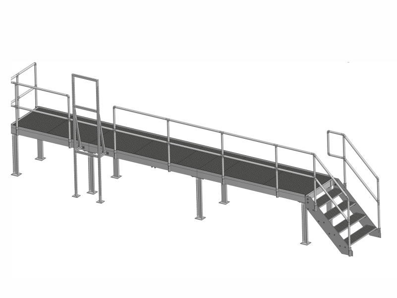
Gallery
» HM 162.15 Extension element of the gallery
» HM 163.14 Gallery
» HM 163.15 Extension element of the gallery
Experimental flume extension element, 2,5m
Water tank, 1100L

UV system for disinfection
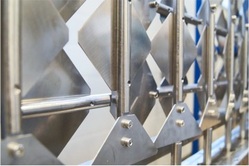
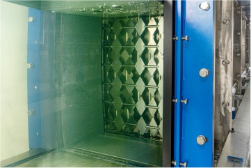
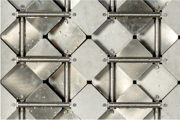
Customised accessory: active grid
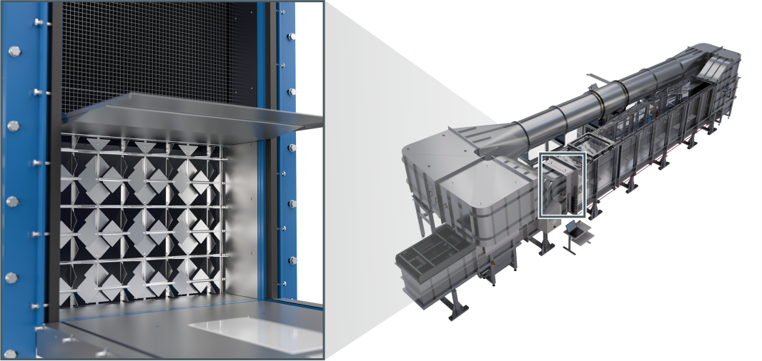
A combined wind/water flume has been constructed by GUNT as a customised solution. An active grid is installed in the water cross-section, which enables controlled turbulent flow conditions. For this purpose, rectangular plates are mounted on vertical and horizontal shafts. The shafts can be rotated individually via motors, resulting in defined cross-sectional contractions and the generation of turbulence.
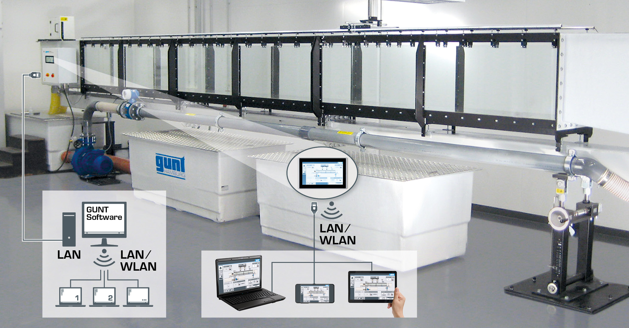
Automated operation and data acquisition
The experimental flumes HM 162, HM 163 and HM 161 are controlled by a PLC via touch screen. PLC-supported accessories are automatically identified and displayed. By means of an integrated router, these two experimental flumes can alternatively be operated via end device. The user interface can also be displayed on other end devices (screen mirroring). Via the PLC, the measured values can be stored internally.
Download