Fluid Line - HM 250 series
Fluid Line - HM 250 Serie
fundamentals of fluid mechanics

SMART features
 |
Intuitive operation and control via touch screen |
 |
Screen mirroring, mirroring of the user interface on additional terminals |
 |
RFID technology, automatic recognition of accessories |
 |
» E‑Learning course, extensive multimedia teaching material |
Overview of the HM 250 series
Real experiments – digital media
The series HM 250 offers a versatile experimental introduction to the fundamentals of fluid mechanics. The digital teaching-learning concept offers an interaction between real experiments and digital teaching with experiment preparation, execution and evaluation.
Due to screen mirroring, students can follow the preparation and execution of experiments on end devices.
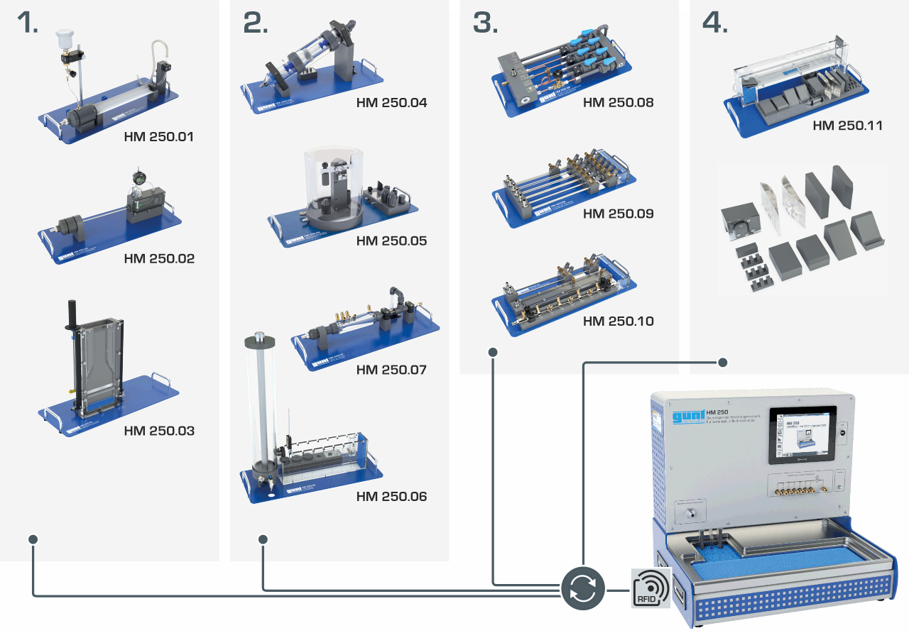
Setup
The HM 250 base module provides the basic supply in each case.
An extensive selection of optionally available accessories enables experiments on the themes:
HM 250 Base module
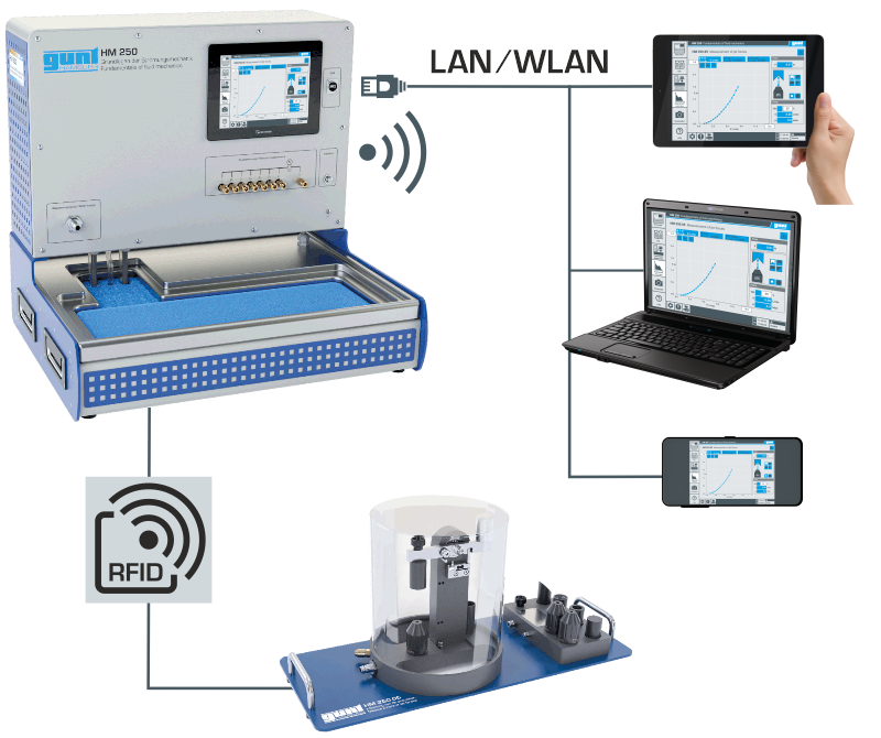
The basic module serves as a supply and operating unit for carrying out various experiments in fluid mechanics. For the individual experiments, HM 250 provides the basic supply via energy- and water-saving technology. Measurement, control and communication systems are also provided by the base module.


- device control with PLC
- intuitive experiment execution via touch screen (HMI)
- screen mirroring on up to 10 end devices: PC, tablet, smartphone
- automatic identification of accessories via RFID technology
Accessories for various themes
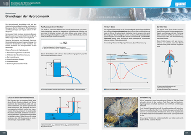
Flow in pipes
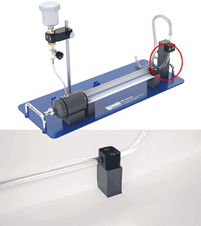
HM 250.01 Visualisation of pipe flow
To visualise laminar and turbulent flow, the Osborne Reynolds experiment is used. The transition from laminar to turbulent flow can be observed above a limiting velocity.
- visualisation of laminar, turbulent and secondary flow
- ink as a contrast medium
- visible flow area through transparent pipe section
- pipe section contains a horizontal, straight pipe and 90° pipe elbow
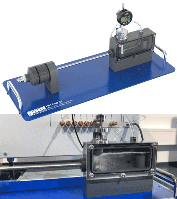
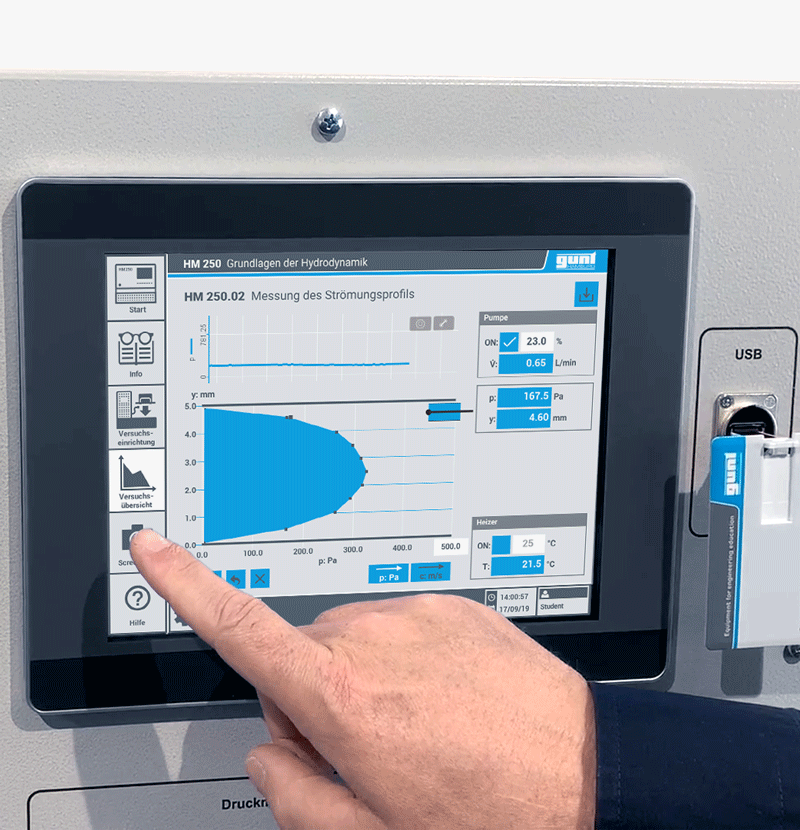
HM 250.02 Measurement of flow profile
Investigation of the flow profile. Differences in the flow formation can thus be detected by the use of measurement technique.
- representation of laminar and turbulent flow profiles
- measurement of the dynamic pressure at various position of the pipe section using a Pitotstatic tube
- influence of viscosity on flow formation due to heating of the water
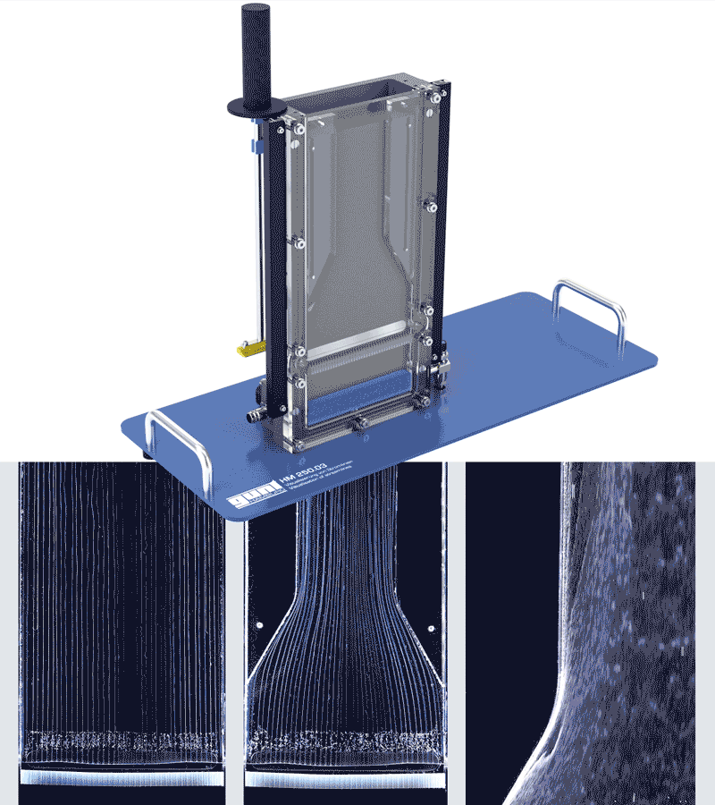
HM 250.03 Visualisation of streamlines
The laminar, two-dimensional flow in the flow channel represents a good approximation to the flow of ideal fluids: the potential flow. Fine gas bubbles are ideal for visualising streamlines. Due to their small size, they are particularly well carried along the flow.
- electrolytically generated hydrogen bubbles visualise streamlines
- visualisation of the streamlines by means of LED lighting
- the concept of streamlines, flow lines and strike lines is developed on the basis of the different bubble sizes
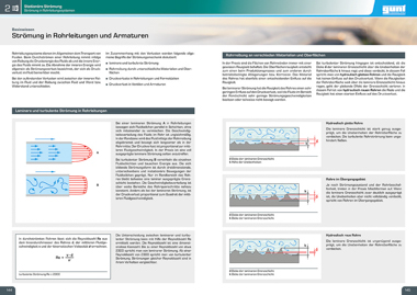
Laws of hydrodynamics
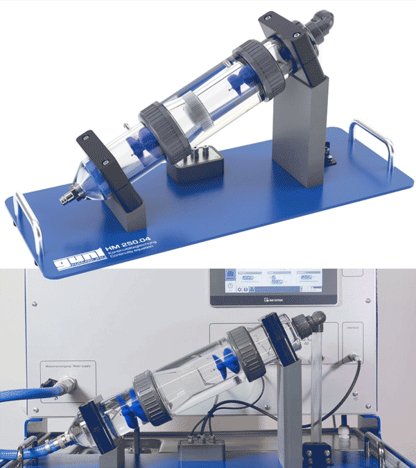
HM 250.04 Continuity equation
In the continuity equation, the relationship between the cross-sectional flow area and the flow velocity is analysed. These physical laws are the foundation of fluid mechanics.
- investigate flow rates at different cross sectional areas
- visible flow chamber due to transparent pipe section
- measurement of flow velocities via impellers
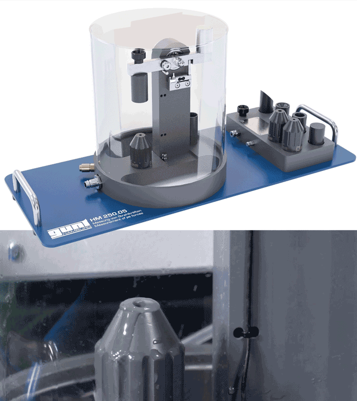
HM 250.05 Measurement of jet forces
Every change in the velocity of a fluid by deflection, deceleration or acceleration is related to a change in momentum. The change in momentum simultaneously causes a force effect. A nozzle is used to create a water jet, which then hits a deflector and can be measured.
- two different nozzles and four different deflectors are available
- investigation of jet forces on deflectors with different deflection angles
- splash guard made of transparent material for observation of experiments

HM 250.06 Free discharge
For horizontal discharge from a tank, the shape of the outlet and the outlet velocity affect the trajectory of the water jet. In hydrodynamics the interaction are described.
- investigation of the trajectory in function of the level in the tank and the shape of the outlet
- determine the trajectory of the water jet with digital depth slide gauge
- resulting trajectory of the water jet is digitally recorded in the transparent experimental section
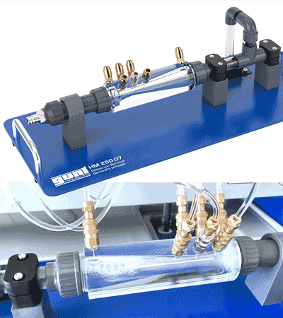
HM 250.07 Bernoulli's principle
Bernoulli's law describes the relationship between the flow velocity of a fluid and its pressure. Thus, an increase in velocity in a flowing fluid leads to a decrease in static pressure and vice versa. The total pressure of the fluid remains constant. Bernoulli's equation is also called the law of conservation of energy of the flow.
- investigation of static, dynamic and total pressure along the Venturi nozzle
- transparent Venturi nozzle with measuring points for measuring static pressures
- by changing the direction of flow, the nozzle can be used as a diffuser
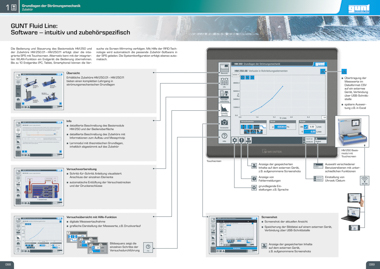
Friction losses in pipe flow

HM 250.08 Losses in pipe elements
Pressure losses in pipe sections can have various causes, such as acceleration, deceleration, deflection or friction. Pressure loss is often caused by a combination of several factors. This must be taken into account when designing piping systems.
- determination and comparison of the pressure losses in different pipe sections
- different pipe sections chosen for their didactic qualities
- individually closable pipe sections with various pipe elements: nozzle, orifice, bends, valve, ball valve
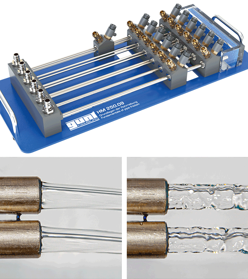
HM 250.09 Fundamentals of pipe friction
Due to internal friction, differences in velocity occur in the flow of fluids. Energy is needed in the form of pressure to overcome these differences. This results in pressure losses in the pipe flow. The internal friction is the decisive factor determining whether the flow in the pipe is laminar or turbulent. The pipe friction factor, a dimensionless number, is used to calculate pressure losses. The friction factor is determined with the aid of the Reynolds number, which describes the ratio of inertial forces to friction forces.
- calculation of pressure losses and determination of the Reynolds number and pipe friction coefficient
- differences in flow formation can be observed on the surface of the outflowing water jet
- influence of viscosity on flow formation due to heating of the water

HM 250.10 Pressure curve along the inlet section
In pipe flow, the surfaces, the cross-sectional geometries and the geometry of the inlet section influence the internal friction and thus also the flow formation. The two key figures Reynolds number and pipe friction coefficient are determined from the measured values and can be displayed in the Moody diagram.
- investigation of pressure losses at the inlet and along the inlet section
- inlet section with streamlined and non-streamlined inlet
- pipes with different geometries and surfaces for further experiments included in scope of delivery
Flow in open channels
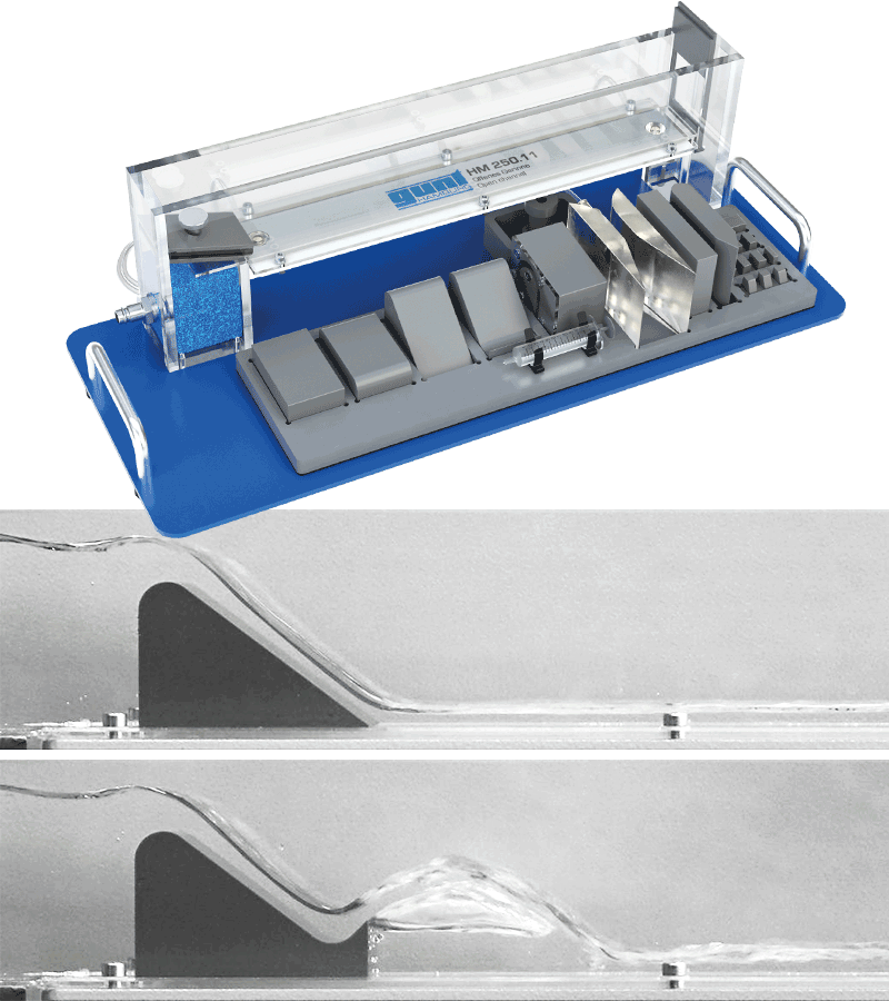
HM 250.11 Open channel
The accessory can be used to demonstrate the effect of various obstacles on the energy level in the open-channel flow. Fundamentals required for the design of artificial shipping channels or for the regulation of rivers and barrages can be taught on a very small scale.
- demonstration of energy levels and losses with different weirs and piers in the transparent experimental flume
- demonstration of energy dissipation in the stilling basin with end sill and dentated sill as well as ogee-crested weir with ski jump
- determination of water levels (energy levels) via digital pressure measurement
Additional accessory
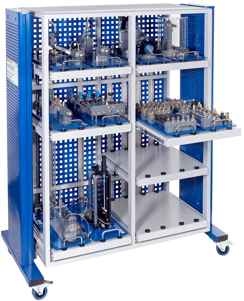
HM 250.90 Laboratory shelf
The robust laboratory shelf allows you to conveniently store experimental equipment and transport it to another location if required.
A safe transport and safe depositing of the laboratory shelf are guaranteed. Brakes on the castors prevent it from rolling away. Due to the snap-in function of the shelves, only one shelf can be pulled out at a time, so that the shelf always has a firm stand.
- robust and safe rack for storage of the HM 250 series
- good overview and quick access to the accessories
- six shelves for low constructions, one shelf for high constructions
SMART Features
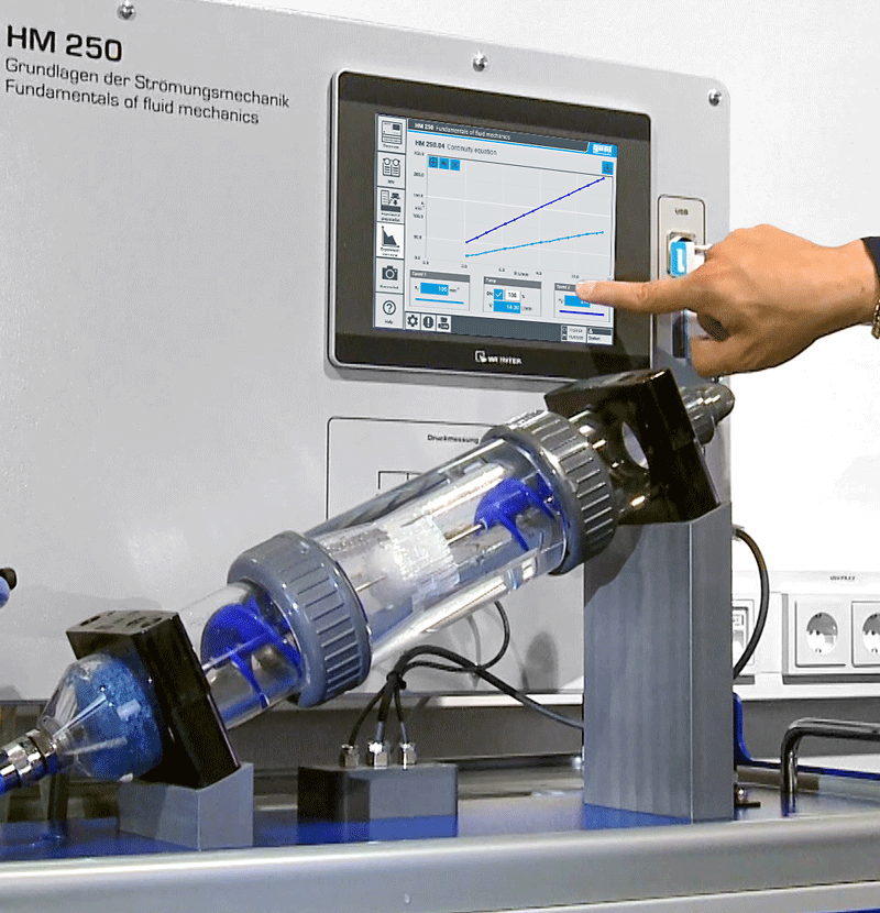
Intuitive operation and control via touch screen
The clear design of the user interface with meaningful symbols enables intuitive operation:
- guided experiment preparation for connecting the individual accessories
- automatic bleeding of the experimental sections and the pressure connections
- help function that visualises the procedure in individual steps
With a detailed description and information on the set-up and measuring principle, the experimental unit can be operated without prior knowledge. Learning modules with theoretical basics supplement the digital information.

Screen mirroring
By means of an integrated WLAN router, the experimental unit can additionally be operated and controlled via one end device and the user interface can be displayed on up to 10 end devices (screen mirroring).
For tracking and evaluation of the experiments, up to 10 external workstations can be used simultaneously using the local network via LAN connection. Independent navigation in the menu is possible on all end devices.

RFID technology
The accessories are simply and safely positioned on the worktop of the base module. After positioning, the base module identifies the respective accessory via RFID technology, automatically selects the appropriate software in the PLC and performs an automatic system configuration.
The appropriate software is displayed in the user interface of the touchscreen.
PLC software in detail
The content of the PLC software is coordinated with the individual accessories. The user interface includes, among other things, a guided experiment preparation, learning modules with theoretical basics as well as a graphic display of the measured values.
Via a USB interface the measured values can be transferred to a PC and stored there (e.g. via MS Excel).


E-Learning course

A free E-Learning course on fluid mechanics enables independent learning of the theoretical fundamentals and follow-up of the experiments.
- multi-media online course, which enables learning independent of time and place
- check through targeted review of the learning objectives
- all content is free of charge - you are welcome to use extracts for your lectures
Download